Crossing Gate
Lab 2
Process
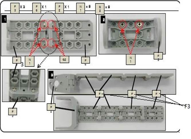
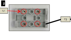
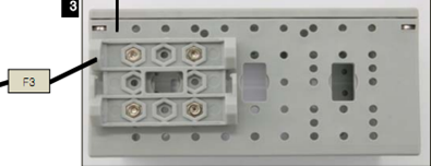
Step 1: Attaching F3, F6 and F2
Take 3 * F3’s, 1* F6 and 1* F2.
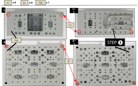
As shown below attach F3, F6 and F2 using 8 * N1 (nuts) and 8 * S1 (screws)
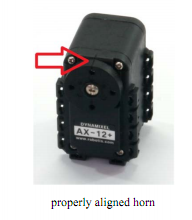
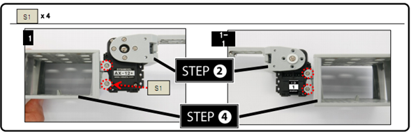
Step 2: Attaching actuator to step 1
Take an Actuator with ID1 and make sure that horn is properly aligned
Attach step 1 to the actuator as shown in the figure using 4 *N1, 4 * S1 and 1 * BU, 1 * WA and 1 *S-B.
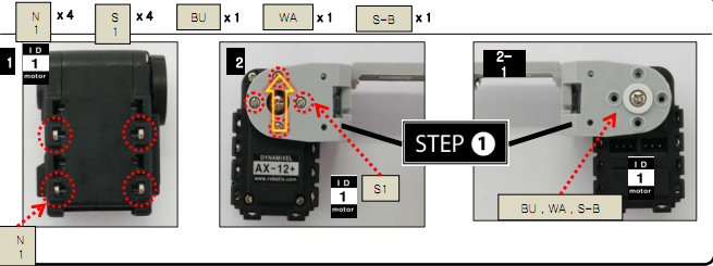
4 * N1 (Nuts) attached are used in step 5
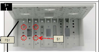
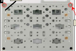
Step 3: Attaching F3 to F51
Attach F3 to F51 using 4 * N1 and 4 * S1.
Insert 4 * N1 into groves of F3 as shown
Attach F3 to F51 *Importance should be given to the direction*
Step 4: Attach Step 3 to F52
Attach Step 3 to F52 using 4*N1 and 4*S1
Step 5: Attach Step 2 to Step 4
Make Sure F52 surface faces up.
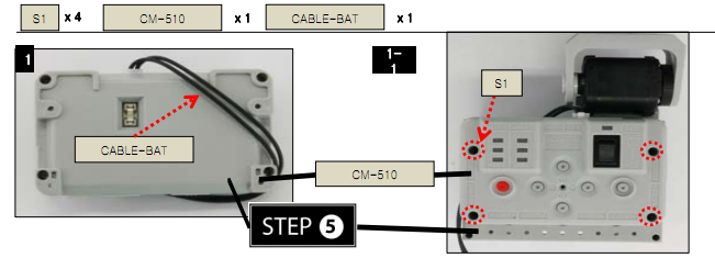
Step 6: Attaching CABLE - BAT wire to CM 510
Insert one end of CABLE – BAT wire into BAT port of CM 510 and attach CM 510 to step 4 using 4*S1 on top of F52.
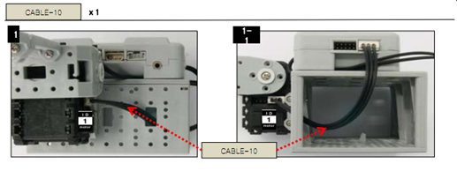
Step 7: Connecting ID1 to CM510
Connect ID1 to CM 510 with CABLE 10 as shown in figure
Step 8: Attaching step 7 to battery
Connect Step 7 to Battery using 2* S12 screws and F60 battery holder.
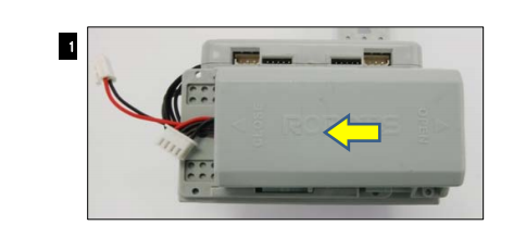
Attach F 60 to Step 7 using 2 * s12 as shown in figure
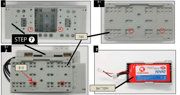
And slide battery into F60
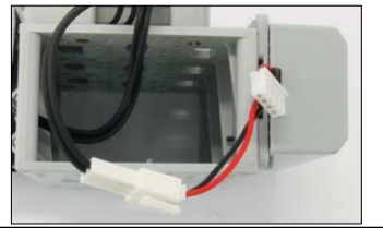
Step 9: Powering up
Connect the other end of CABLE – BAT used in Step 6 to the battery as shown in figure
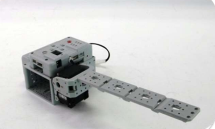
Finished Product: