Excavator
Lab 6
Process
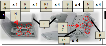
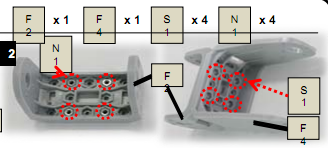
Step 1: Inserting N1 into actuators
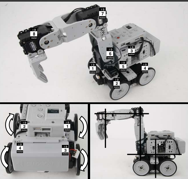
Take actuators with ID 1; ID 2; ID 3; ID 4; and insert N1 as shown in figure
Make sure that horn position is properly aligned.
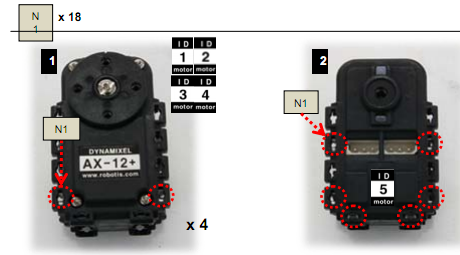
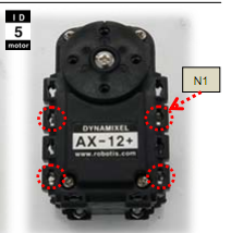
Insert N1 into actuator with ID 5 as shown in figure
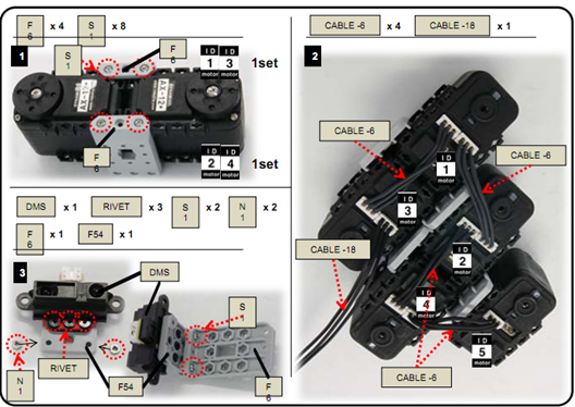
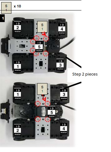
Step 2: Attaching step 1 to F6, F54 and DMS together.
Attach step 1 to F6, F54 and DMS together as shown in figure
- ID 1 and ID 3 as one set and ID 2 and ID 4 as another set
- Connect ID4 to ID5; ID2 to ID4; ID1 to ID2; ID1 to ID3 with four CABLE-6 wires and Connect ID 3 with CABLE-18.
- Connect DMS using Rivet as shown in figure
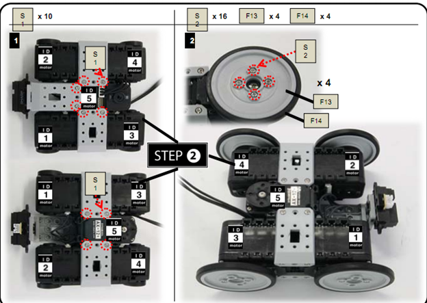
Step 3: Attaching pieces
Attach together all the pieces formed through step2 as shown in figure
Attach F13 and F 14 as shown in the figure
Step 4: Attaching
- Attach F3, F4 and F10 together
- Attach F2 to F4
- Attach F3, F9, and F11 together

Step 5:
Take actuators with ID6; ID7 and ID 8 and make sure that the horn position is properly aligned and insert N1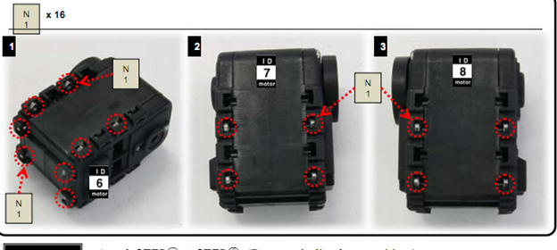
Step 6:Attaching step 4 with step 5
- Attach step 4 with step 5
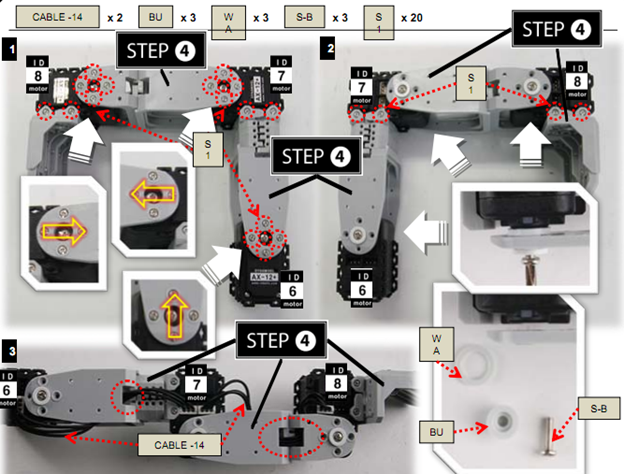
- With CABLE-14 connect ID6 to ID7; ID7 to ID8
Step 7: Attach step 6, F 10, F54 and IR sensors together
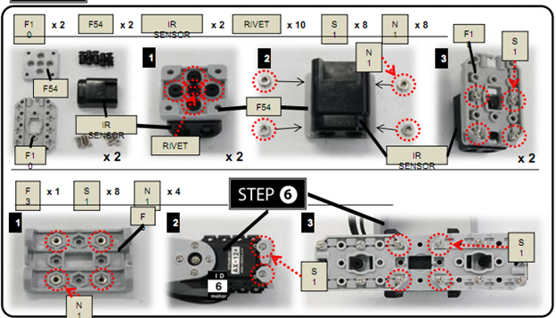
Note: Make * 2
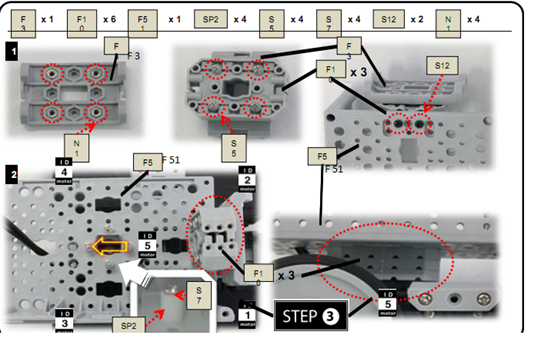
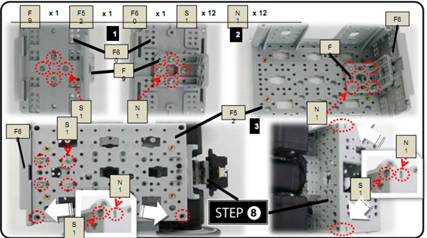
Step 8: Attach STEP 3, F3, F10, and F51 together
Here we attach F3, F10 and F51 on top of step3 as shown in figure
Step 9: Attaching F9, F52 and F60 to step 8
Step 10: Attaching pieces
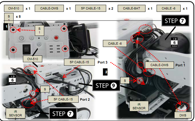
- Attach STEP7, STEP9, and CM-510 together.
- With 2 5P CABLE-15:
- Connect IR SENSOR1 to Port 3 of CM-510; IR SENSOR2 to Port 2 of CM-510.
- Connect DMS to Port 1 of CM-510 with CABLE-DMS
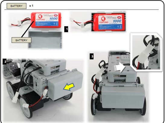
Step 11: Connecting Battery
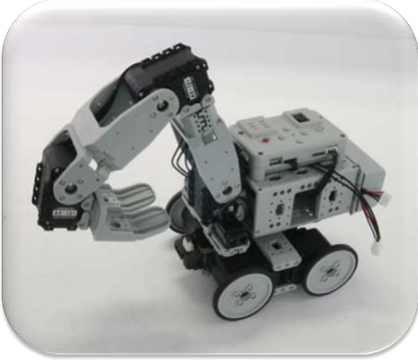
Final Product:
Assembly Check:
Step 1: Run the assembly check program
Set the robot in PLAY mode; hold the D button then press START.
Once the START button is pressed, the assembly check program begins.
Step 2: AX12+ initial position and ID check
Select each actuator separately and compare it to the picture below.
Ensure the actuators’ horns are properly aligned (the horn’s notch should be aligned with the actuator’s).
Pressing the U or D button selects one actuator at a time.
The selected actuator’s LED lights up and goes to its initial position.
Check starts from ID1.
U moves to the next ID in ascending numerical order; D, in descending numerical order.
If the actuator’s ID does not exist then the robot beeps.
Although the LED may lit, if there is no power then check the wiring on the actuator.
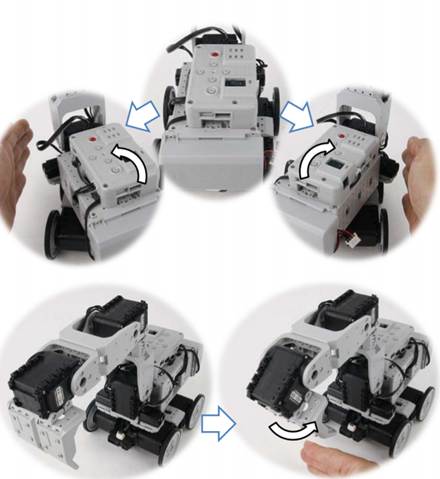
Step 3: Sensor and behavior check
From STEP② press R. The robot returns to its initial position as pictured above.
Place your hand close to the sensors as pictured below. Robot behavior begins.
If the robot does not behave as pictured below, then check the sensor wiring and its port.
Pressing L will return the robot back to STEP②.