Distance level Meter
Lab 4
Process
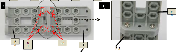
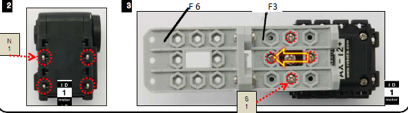
Step 1: Attaching ID1, F3 and F6 together
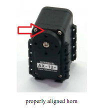
Take an actuator with ID1 and make sure horn position is properly aligned.
Attach F3 and F6 as shown in the figure using 2*N1’s and 2 * S1’s.
Attach the above to the actuator as shown in the figure
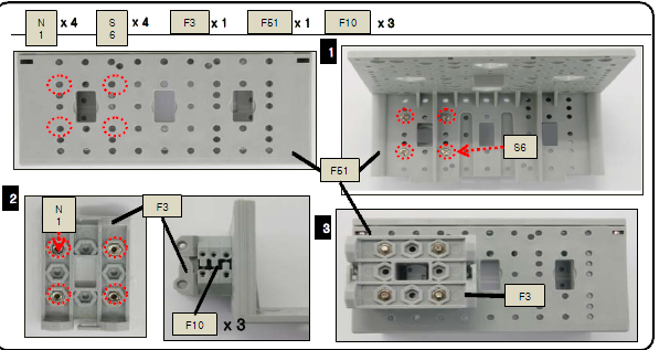
Step 2: Attach F3, F10 and F51 together as shown in the figure
Importance should be given to the direction
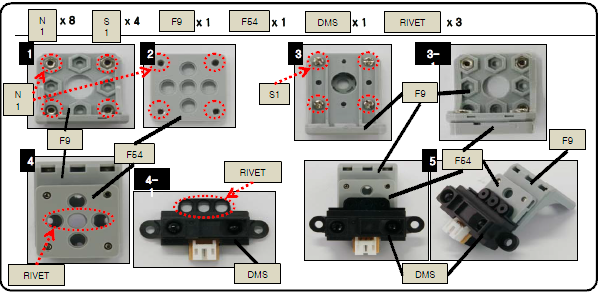
Step 3: Attach F9, F54 and DMS together
Attach F64 on F9 as shown in figure and attach DMS to it using rivet as shown in figure.
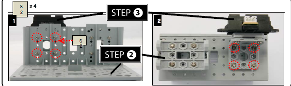
Step 4: Attach step 2 to Step 3 as shown in figure
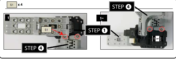
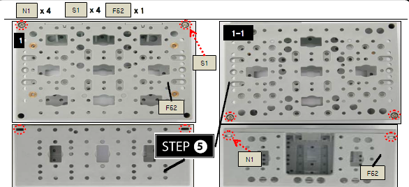
Step 5: Attach Step 1 to Step 4
Step 6: Attach Step 5 to F52
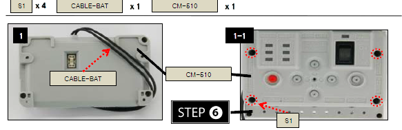
Step 7: Attaching CM 510
Attach CM 510 on top of F 52 along with CABLE –BAT
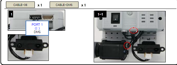
Step 8: Attaching cables
Connect ID1 To CM – 510 with cable 06
Connect DMS to port1 of CM-510 with CABLE- DMS
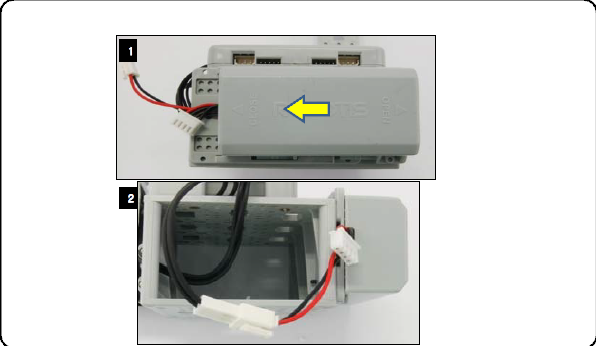
Step 9: Attach step 8 to Battery Holder
Attach step 8 to battery holder as shown in the figure
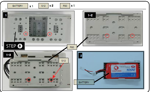
Step 10: Connect the Battery through the battery cable
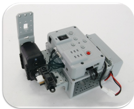
Finished Product:
Assembly Check:
Step 1: Running the assembly check program
Set the robot in PLAY mode; hold the D button then press START.
Once the START button is pressed, the assembly check program begins.
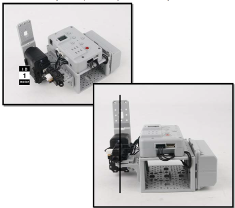
Step 2: AX12+ initial position and ID check
Select each actuator separately and compare it to the picture below.
Ensure the actuators’ horns are properly aligned (the horn’s notch should be aligned with the actuator’s).
Pressing the U or D button selects one actuator at a time.
The selected actuator’s LED lights up and goes to its initial position.
Check starts from ID1.
U moves to the next ID in ascending numerical order; D, in descending numerical order.
If the actuator’s ID does not exist then the robot beeps.
Although the LED may lit, if there is no power then check the wiring on the actuator.
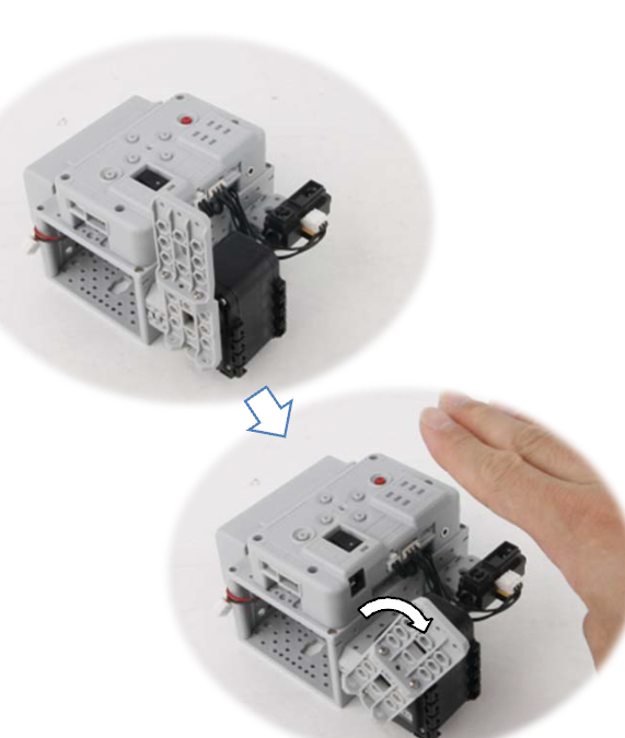
Step 3: Sensor and behavior check
From STEP 2 press R. The robot returns to its initial position as pictured above.
Place your hand close to the sensors as pictured below. Robot behavior begins.
If the robot does not behave as pictured below, then check the sensor wiring and its port.
Pressing L will return the robot back to STEP 2.